Contemporary CNC machining combines advanced technology with perfect planning.
However, before the detail goes to the machine, proper preparation of the design file is crucial.
It is the quality of the 3D and 2D documentation that determines whether the component will be produced as expected, on time and without unnecessary revisions.
In this guide, Eurotech CNC experts explain step-by-step how to prepare the model correctly, what formats are recommended, what to pay attention to in construction and how to avoid mistakes that increase lead times.
Why is proper file preparation so important?
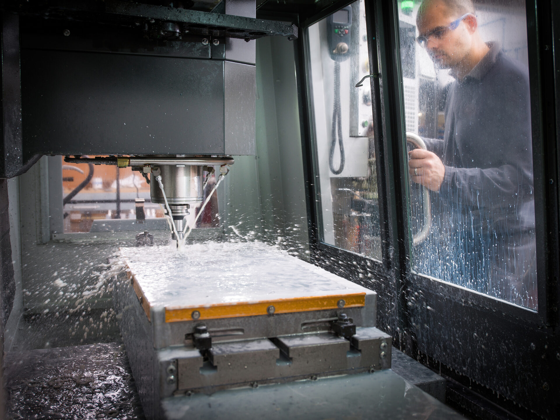
In the process CNC milling every micron matters.
An incorrect CAD model, a lack of tolerances or an under-specified material can result:
- the need for reprogramming,
- Increasing lead times,
- and, in extreme cases, the execution of a non-conforming detail.
A well-prepared design file is a guarantee of a smooth transition from the design phase to production, fewer errors and optimum manufacturing cost.
Step 1: Choose the right CAD software
The first step is to create a 3D model in CAD software (e.g. SolidWorks, Autodesk Inventor, Siemens NX, Fusion 360).
It is important that the builder works in an environment that allows the export of files in standard formats supported by CNC machine tools.
Most commonly used formats:
- STEP (.stp, .step) - versatile, accurate and preferred by most machining facilities,
- IGES (.igs) - older, but still useful for simple geometries,
- Parasolid (.x_t, .x_b) - popular in the SolidWorks and NX environments,
- DWG/DXF - used for 2D drawings, e.g. flat parts for laser cutting.
Avoid native formats (e.g. .sldprt, .ipt) if the file is to go to an external contractor - they may not be compatible with their system.
Step 2. Establish technological parameters already at the design stage
When designing a workpiece for machining, it is worth remembering that every geometry has its own technological limitations.
The most common design mistakes:
- too small corner radii, which cannot be achieved with a standard cutter,
- walls that are too thin (less than 1 mm) and may deform,
- excessive pocket depths with insufficient detail stiffness,
- unsuitable holes for drilling tools.
Practical Tip:
If in doubt, consult a technologist on the design - it is often possible to reduce the cost and production time by as much as 20-30% already at this stage.
Step 3: Define the material and its properties
Each material behaves differently during processing.
Therefore, the design file should contain unambiguous information about the material from which the detail is to be made.
The most commonly used materials in precision metalworking are:
- aluminium (lightweight, easy to process and economical),
- structural and stainless steel,
- brass and copper,
- titanium alloys (for the aerospace and medical industries).
Including this data in the documentation allows the appropriate cutting parameters, cooling and tools to be selected - which directly affects the quality and cost of the implementation.
Step 4 Prepare a 2D technical drawing
Although the 3D model is the basis of machine programming, 2D drawing still plays a key role.
This is where the information that is not visible in the model is placed:
- dimensional tolerances,
- surface roughness,
- threads and through holes,
- Phase angles, radii,
- the required finishes (e.g. anodising, grinding, polishing).
The drawing is best saved in PDF + DWG/DXF format.
Such a set eliminates the risk of data misinterpretation by the CAM programme.
Step 5. Keep units and reference axes consistent
One of the most common problems when preparing a file is inconsistent units (mm/inch) or the lack of a defined zero point.
Before you submit your project, make sure that:
- all dimensions are in millimetres,
- the model has a base point (0,0,0) at a logical location - e.g. in a corner or on a mounting plane,
- The X, Y and Z axes correspond to the orientation in which the workpiece will be machined.
Neglecting this step is a common cause of production errors and the need for re-programming.
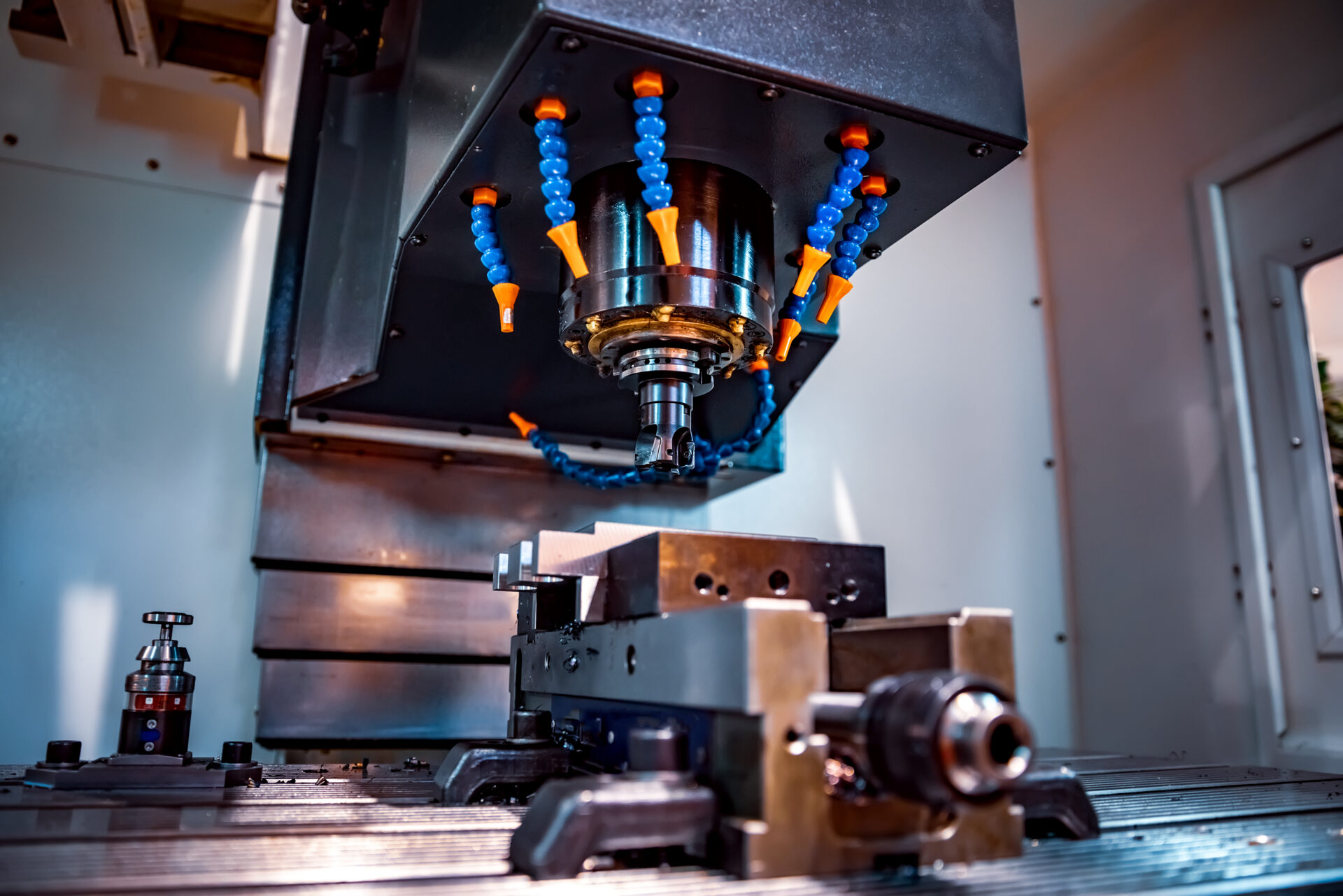
Step 6 Take into account the capabilities of the machine tool
Depending on the type of machine, geometry parameters may need to be adjusted.
For example:
- In CNC milling, the maximum pocket depth depends on the length of the cutter,
- In CNC turning, the diameter and length of the workpiece must be matched to the chuck and tools,
- in 5-axis processing, it is worth optimising the orientation to avoid collisions.
Therefore, when preparing your file, it is worth consulting your contractor - Eurotech CNC's experienced technologists will be happy to advise you on how to optimise your project for their machinery.
Step 7 Verification and export
Before you send the file, carry out a final check. Check:
- completeness of the model and absence of „holes” in the surfaces,
- compliance of tolerances with the drawing,
- orientation and position relative to the zero point,
- correctness of file names (avoid Polish characters and spaces).
It is good practice to include a short description or a PDF document with the information:
- number of pieces,
- finishing required,
- implementation priority (prototype / series).
A data package prepared in this way allows programming to begin almost immediately on receipt of the documentation.
Why cooperate with Eurotech CNC already at the design stage?
Experienced technologists Eurotech CNC analyse each uploaded file for:
- feasibility of the geometry,
- optimum selection of tools and parameters,
- opportunities to reduce processing times.
This not only provides clients with a quote, but also technology recommendations that often translate into lower cost and better quality.
Working with a company that understands both the design and the production process is a guarantee of efficiency and seamless implementation.
Correct preparation of the design file is the first step to success in CNC machining.
Well-drafted documentation minimises errors, reduces lead times and achieves maximum precision.
If you want to be sure that your project will be executed flawlessly, contact Eurotech CNC.
Upload your CAD file - the expert team will analyse it, advise on the best solutions and prepare a professional quote.
Frequently Asked Questions (FAQ)
Preferably in STEP (.stp) or IGES (.igs) format - they are universal and compatible with most CAD/CAM systems.
Yes, a technical drawing with tolerances and surface description facilitates quality control and speeds up the production process.
The Eurotech CNC team offers support in refining the design and technological advice before machining.
Yes - the company carries out both prototypes and production runs, helping to optimise the design before implementation.